 ®
 ®
 ®
01
Customer requirements
Input reference illustration
Start with the engine application, cylinder-head information, samples and the intended development goal.
CUSTOM FORGED PISTONS
From a sample to a new idea, the conversation starts with your engine.
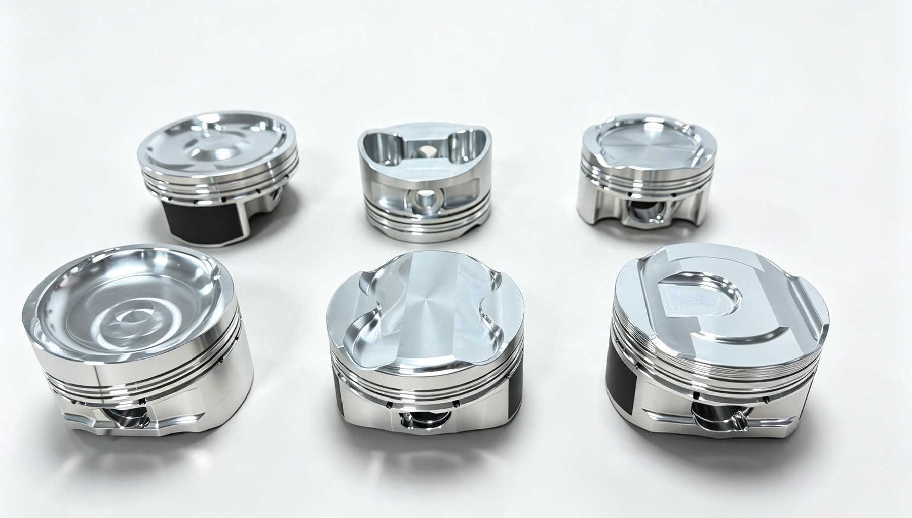
Start with your engine model and intended application.
Use an existing piston as the starting point for discussion.
Discuss a new geometry or a specific development brief.
DESIGNED AROUND YOUR ENGINE
Your cylinder head helps define the piston. We use the combustion-chamber shape and valve layout as inputs for piston crown and valve-relief design.
Review the chamber, valve arrangement and the available reference information.
Develop the crown geometry and valve-relief layout around the engine requirements.
Review cam lift, timing, assembly dimensions and required operating clearances before finalising the design.
CYLINDER HEAD TO VALVE RELIEF
Customer cylinder-head information guides the 2D layout and 3D piston-and-valve review. Valve reliefs are refined through repeated checks.
Illustrations have identifying text and dimensions removed for public display. Final clearance is checked against the original engineering files, valve lift, timing and assembly requirements.
SAMPLE TO DESIGN
A customer-supplied cast OEM sample provides the reference for defining geometry and developing a forged-piston CAD design.
Left: JND forged-piston CAD design
Right: customer-supplied cast OEM sample
FROM DEVELOPMENT TO PRODUCT
A piston-blank development route, shown through structural illustrations and manufacturing photographs.
Input reference illustration
Start with the engine application, cylinder-head information, samples and the intended development goal.
2D engineering design
The drawing connects cylinder-head references with the piston geometry.
Piston CAD design
Crown, ring grooves, pin bore and skirt geometry are reviewed before blank preparation.
Actual blanks and production cell
After the 3D design is confirmed, blanks are prepared for the agreed manufacturing route.
Robotic production cell · 7 seconds
Robotic handling connects blank loading with the subsequent machining process.
Existing finished-product reference · not this project
Review the finished part against the agreed specifications before the delivery arrangements are confirmed.
Cylinder-head geometry and customer requirements inform drawing development, 3D review, blank preparation and machining. Final geometry and manufacturing specifications follow the agreed project drawings. The finished-product image is a reference from the existing range.
Discuss your development projectDESIGN CONVERSATION
Crown volume, valve clearance and combustion-chamber context.
Pin dimensions and the interfaces that need to work together.
Ring dimensions and groove requirements.
Intended use, thermal conditions and material selection.
No. Start with what you know. The engine model, intended use, sample availability and approximate quantity help frame the project.
Yes, after agreeing a suitable communication channel and any confidentiality requirements. Do not put confidential drawings in a public message.
They depend on the agreed design, quantity and development requirements, and are confirmed in the project quotation.
YOUR BRIEF. THE RIGHT DETAILS.
Bring the cylinder-head details, stroke, rod length and target compression ratio. These inputs guide the crown, compression height and component specification.
Explore this detail ↗Choose the route around the geometry, quantity and development requirements. The illustrated cylinder-head case uses a piston blank.
Explore this detail ↗Discuss alloy grade, pin material, ring pack, coatings, clearances and weight matching before the manufacturing specification is approved.
Explore this detail ↗GEOMETRY & FIT
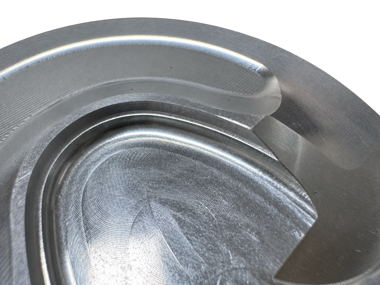
Selected models use a zero-offset pin and retain material below the crown for valve-pocket machining. Crown designs can accommodate larger valves and high-lift camshafts, subject to the specified engine combination.
Most designs use an offset pin to help reduce cold-start noise. Strut-style skirt designs balance wear, noise and rocking control; selected applications can operate at clearances such as 0.004 in.
Compression-height options support short- and long-stroke combinations. Pressure-balance grooves and project-specific valve reliefs address different aspects of the piston design.
Features vary by model and application. Final alloy, components, clearances and installation requirements follow the confirmed product specification. Horsepower examples describe specific project configurations, not a universal piston rating.
APPLICATIONS & CUSTOM DEVELOPMENT

Replacement and upgrade solutions cover selected Japanese, European and American performance engine platforms, with application-specific matching for competitive and high-performance street builds.
Specialist aluminium and steel piston designs address the high-temperature, high-pressure loads of diesel-racing applications. The design and material are selected for each project.
Custom piston development supports specific dimensions, compression ratios and engine combinations, with a flexible approach to project requirements and cost planning.
YOUR NEXT PROJECT